Donkey
Air Conditioning Ductwork Design
The computer program DONKEY determines the size of a duct network, carries out a complete acoustical analysis and determines quantities for costing purposes. The program operates via a set of add on menus in AutoCAD. The user enters the duct layout as a line diagram including all the terminals, fittings and the fan. All the parameters relating to these components including air quantities, duct insulation, sizing method, fan type, etc; are entered in dialogue boxes that are called up on screen. Once the duct layout is entered on the drawing the program will then calculate the duct sizes and the noise levels throughout the system. These results can then be selectively displayed on the drawing or printed from a text file.

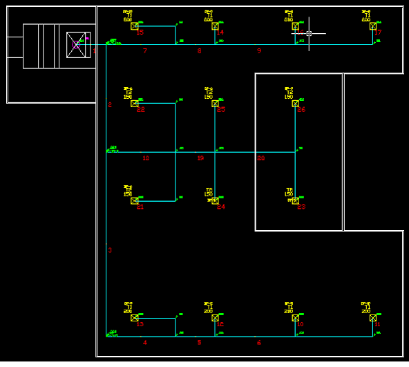
Typical DONKEY Duct Layout
The program has many features that make the inputting of data quite simple including automatic connection of run out ducts to terminals, automatic insertion of fittings and many other features. These enable the powerful and very comprehensive calculations of the program DONKEY to be utilised. Various alternative designs can be quickly and thoroughly investigated and a cost effective design achieved that satisfies the design objective for noise with minimal damper balancing pressure and cost.
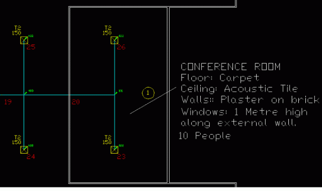
The Conference Room with Listener at Position 1
Ducts are drawn, the fan, terminals and fittings are inserted via a series of pull down menus. These menus also cater for the entry of VAV boxes and plenums and provides for the nomination of a listener position for the detailed noise calculations.
The data for the calculations is extracted from the drawing and the calculations performed via items on the Utilities Menu
The overall results including duct sizes, pressure drops terminal NR levels, damper out-of-balance pressures and noise levels at selected frequencies can all be displayed on screen on the actual duct layout drawing. In addition detailed results for individual terminals, fittings and the fan can be displayed selectively in convenient list boxes.
Quantities for costing including the weight of sheet metal, the number of terminals, dampers, etc. fabrication erection and shop drawing manhours can also be displayed to enable the user to find cost effective solutions.
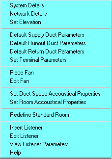
System Menu
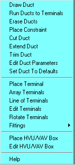
Supply Ducts Menu
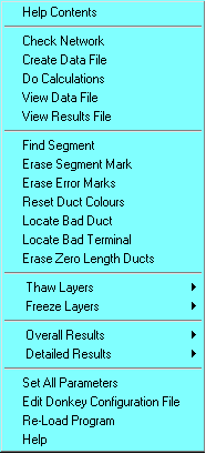
Utils Menu
Supply and Return networks can be entered and in duct coils and silencers can be entered.
Fitings (Bends, Divided Flow, Combined Flow, Dampers, etc.) are selected from Slide Boxes and the program calculates the pressure loss, self generated noise level and attenuation of all of these fittings.
Fittings are selected from slide boxes and placed manually or the program can automatically place bends and branch fittings over areas of the layout nominated by the user
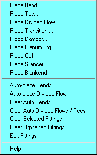
Fittings Menu
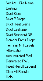
Summary Results Menu

Detailed Results Menu
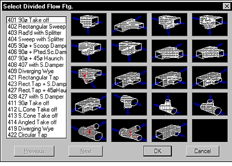
The Place Divided Flow Fitting Selection Box
For the acoustical analysis the program assumes a “standard” 3m x 3m typical room under each terminal, taking into account the self generated noise and the attenuation of all duct elements in the network. From this the program determines sound transmission throughout the whole network and then displays sound pressure levels and NR levels in each “room”.
Alternatively the user can specify “Special rooms” with use defined acoustical properties and up to 6 ducts and 6 terminals in each room.
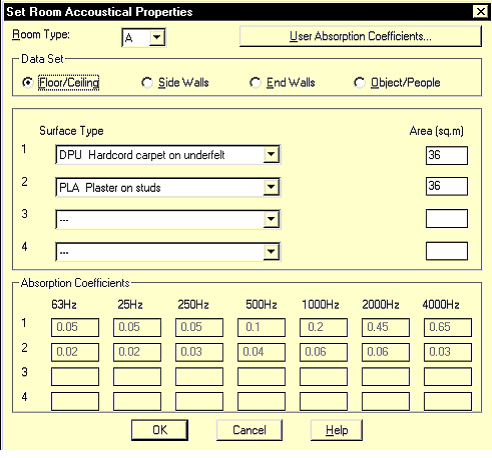
Setting a Special Room Acoustic Properties
After the duct layout has been drawn, the program extracts the information from the drawing, numbers the ducts and produces a file in a format suitable for the calculation program. The calculation program then sizes the ducts and determines the noise level at each terminal and the noise breaking out from each duct.
The overall results can be selectively displayed on the drawing whilst detailed results for specific items (terminals, the fan, etc.) are selectively displayed in dialogue boxes.
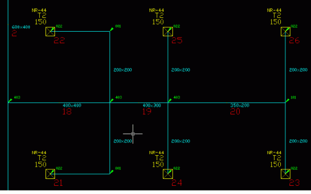
Typical Overall Results Displaying Duct sizes and Terminal NR Levels
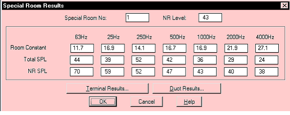
Typical Detailed Results for a Special Room
Technical Details
- The ductwork system and with some limitations different parts of the system can be sized by any of three sizing methods, static regain, constant pressure gradient or balanced pressure drop.
- The program incorporates pressure loss data for a wide range of fittings and balancing dampers can be manually or automatically inserted.
- For rectangular ducting, practical size selections are made avoiding where possible more than one dimension being changed between duct segments. Provision is also made for fixing a duct’s dimensions or velocity.
- Duct leakage can be allowed for on the basis of a l/s per joint per kilopascal pressure difference. Duct heat gains (or losses) with compensating adjustments to air quantities can also be allowed for, if required.
- Interaction between fittings in close proximity can be accounted for.
- The sound power levels throughout the entire network are calculated at each of the seven octave band frequencies from 63 to 4000 Hz taking into account noise generated by the fan, ducts, fittings, VAV boxes, registers, grilles and the noise attenuation of ducts, fittings, plenums and any duct silencers specified. Account is taken of noise transmitted both from the fan down to the terminals and from the terminals back up the network.
- The noise level algorithms in the program are very comprehensive many being quite unique and representing the very latest methodology available.
- Noise levels in terms of an NR level and a sound pressure level can be determined at any location in up to 9 user defined rooms. The acoustical properties of these rooms are determined from the entered quantity and material types of all components in the room including any people or objects.
- The program has a range of material absorption coefficients and transmission loss data readily accessible through drop down lists. In addition users can define their own material acoustical properties.
- The ‘break out’ NR level is calculated for each duct individually on the basis of the duct being located in the ceiling space above the ‘standard’ room.
- The total weight of sheet metal and the fabrication, erection and shop drawing manhours are determined for the ductwork and fittings and all other entered items (eg silencers, dampers, terminals and VAV boxes.
- Comprehensive range and data checking is provided on all input items in the various dialogue boxes. A comprehensive check on the entered duct layout can be carried out prior to the calculations, to ensure ducts are connected, correct fittings have been used, fittings have not been omitted, etc.
- Comprehensive help is provided in all dialogue boxes and on each drop down menu describing the various commands and input time.

