Coilsim
Dynamic Simulation of Finned Tube Heat Exchangers.
COILSIM is a simulation program which allows a complete performance evaluation of any finned tube heat exchanger at full or part load. The program was written by G.J. Van Aken in Canberra. It models forced convection heat transfer and applies to heating as well as to cooling, with or without dehumidification.
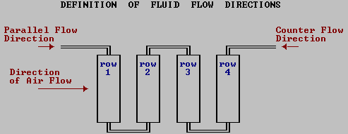
Cooling or heating coil arrangements with up to 12 rows can be modelled for a wide range of cooling or heating fluid types, fluid and face velocities, fluid temperatures and air conditions. A variety of fluid circuits are available for selection which may be arranged for either parallel or counter flow.
COILSIM is not a replacement for coil selection procedures but is intended to simulate the performance of a given coil under a given set of conditions. The program is useful for establishing the performance of a given coil for which the operating conditions are known or for fluids for which there are no operating data available. Thus it avoids the doubtful technique of interpolating or extrapolating tabulated data.

INPUT DATA REQUIRED
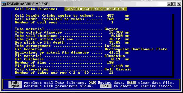
All input data is interactively entered through the keyboard as prompted by the screen panels. Generally the input data requested by the panels are:
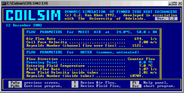
Coil width and height, and number of rows; Tube material, dimensions, spacing and row spacing; Fin material, thickness and spacing; Coil circuiting; Air flow rates and entering conditions; Cooling or heating fluid type, flow rates, direction of flow and fluid temperatures.
The program provides default values wherever this is practical and all data entered is checked against valid ranges. Data files are maintained by the program so that data does not have to be re-entered for the same coil. All thermo-physical properties and heat transfer parameters are derived by the program on the basis of the above data.

Typical Input of Coil Parameters

Typical Input of Flow Parameters

THE SIMULATION
The progress of the simulation are shown on the screen in terms of heat transfer to or from the air stream and heating or cooling fluid, leaving air condition, and fluid return temperature. All initial temperatures are set to that of the entering air with a resulting initial imbalance in heat transfer shown by the air stream and return fluid flow. The time taken to reach equilibrium or steady state heat transfer is a function of coil materials, size and configuration, and fluid flow rates.

The Simulation
The steady state conditions throughout the coil are summarised at the end of the run and transient conditions throughout the simulation procedure are recorded in a data file nominated by the user for subsequent listing or plotting.
The procedure establishes the temperature gradients throughout the fluids, tubes, and fins. It consequently establishes the true surface temperatures throughout the coil and, besides computing the rate of heat and mass transfer for each row, the procedure also shows the results due to all time lags associated with heat storage and fluid flow.
THE RESULTS
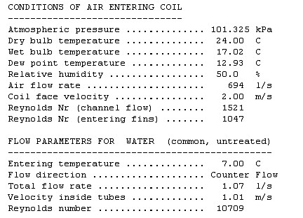
The input data and results are listed in separate files that can be viewed and printed using WordPad or similar WINDOWS package.

Typical Results
The COILSIM(c) simulation procedure is the result of the author’s work on his thesis on “Transient Modelling of Finned Tube Heat Exchangers” in which the modelling techniques, as employed in this program, are fully described.
In summary, the fins are divided into three elements, each operating at its individual transient temperature which are derived by considering the heat transfer between fin elements, and between the coil material and air or fluid streams.
The simulation procedure will run for the duration nominated by the user. During the simulation procedure the temperatures and heat flow rates for the fluid and air sides are displayed. Convergence of the two heat flow rates indicates the approach to steady state operation. Typically 20 or 30 seconds real time is required to reach equilibrium.
The temperature trends during the procedure will be recorded in a data file, nominated by the user, for subsequent listing or plotting these by using the DYNSIM(c) program SIMANAL(c).
Heat transfer coefficients for the air stream are divided into four regions defined as:
- Developing laminar flow,
- Fully developed laminar flow,
- Enhanced heat transfer due to the U-shaped vortices around the tubes,
- Reduced heat transfer at the down stream side of the tubes.
For the practical range of face velocities, the flow between the fins is always in the laminar range and the program has been modelled as such. For this reason the air flow rates are restricted by the program to a maximum Reynolds number of 4000 as determined for channel flow.
No restrictions are placed on heat transfer fluid velocities, apart from that it must be greater than zero. Flow direction is handled in the program with the “counter flow” or “parallel flow” indicator set by the user. The program will therefore model heat transfer for fluid flow in the laminar as well as the turbulent region. However, warnings will be issued when the fluid flow is in the laminar or transient range. Good results can be expected for either the laminar or turbulent range, but for the transient range the heat transfer coefficients are averaged from those derived for laminar and turbulent flow. Therefore simulation results with fluid flow in the transient region must be interpreted as being INDICATIVE ONLY. In practice, coils operating in the transient flow region tend to produce unstable control.
All programs in the COILSIM(c) suite are self explanatory and are supplemented with help panels where necessary. No external documentation is required to run these programs.

